Week 13, Assignment 13
Input Devices
Video - Week Thirteen, Lecture Thirteen
Goal
This week’s assignment is to get familiar with a range of different sensors and how to make use of them and finally add a sensor to a microcontroller board that I have designed and take input through it.
Introduction
An Input device is a device or sensor which gives Data and controls the signals from Micro-Controller and reads the information sent by these Input Devices. Input Devices or Sensors are electronic devices used to sense or measure quantities like distance, heat, temperature, pressure, speed, etc. Some other examples of input devices can be a switch, keyboard, Joysticks, camera, scanner, and some other different real world parameters to measure.
I was very curious about different types of sensors that we saw in lecture, but then I realized that not all of them are relative to kind of “sensing” that my final project will require. So, as I saw this week as a good opportunity to develop my own experimental Input Device and make an important update to my final project. I then decided to use an IR Proximity Sensor which I will be using in my Final Project also for detecting the Pineapple placed at the middle of the Deshelling Machine and to adjust the cutter accordingly for deshelling the pineapple. Still I decided to use an Ultrasonic Sensor also as it was also another option to serve the purpose for my machine, over that out of curiosity I will be going through with number of sensors first.
Types of Sensors:
Photo Transistor:
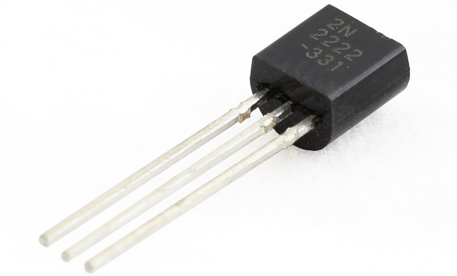
A phototransistor is a light-sensitive transistor. It is a bipolar transistor encased in a transparent case so that light can reach the base–collector junction. A typical transistor consists of a collector, emitter, and base sections. The collector is biased positively with respect to the emitter and the base-collector junction is reverse biased. A phototransistor remains inactive until light falls onto the base.
Motion Detection Sensor:
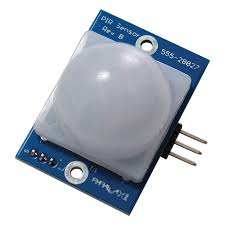
A passive infrared sensor (PIR sensor) is an electronic sensor that measures infrared (IR) light radiating from objects in its field of view. They are most often used in PIR-based motion detectors. These sensors detect activity it’s not a proximity detector but it is activity detector. It has several nice features including sensitivity adjustment and trigger delay. Qualitative measurement of activity is done in this sensor. This sensor requires a 5V DC supply. It can be used to sense the person while he moves, but sensitivity of the device can be an issue.
Thermistor:
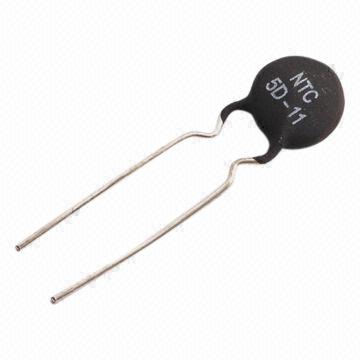
The word itself tells that it is a thermally sensitive resistor, and it changes its resistance according to the surrounding temperature. Thermistors are widely used as inrush current limiter, temperature sensors (Negative Temperature Coefficient or NTC type typically), self-resetting overcurrent protectors, and self-regulating heating elements (Positive Temperature Coefficient or PTC type typically).
Ultrasonic Sensor
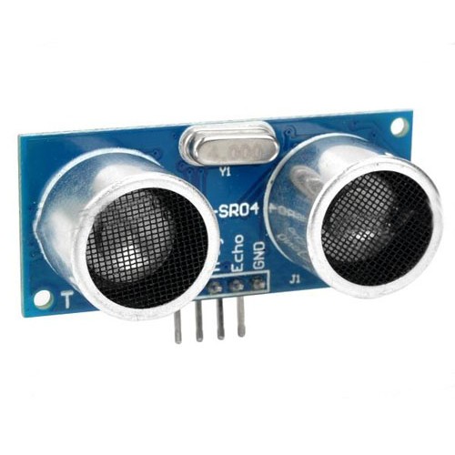
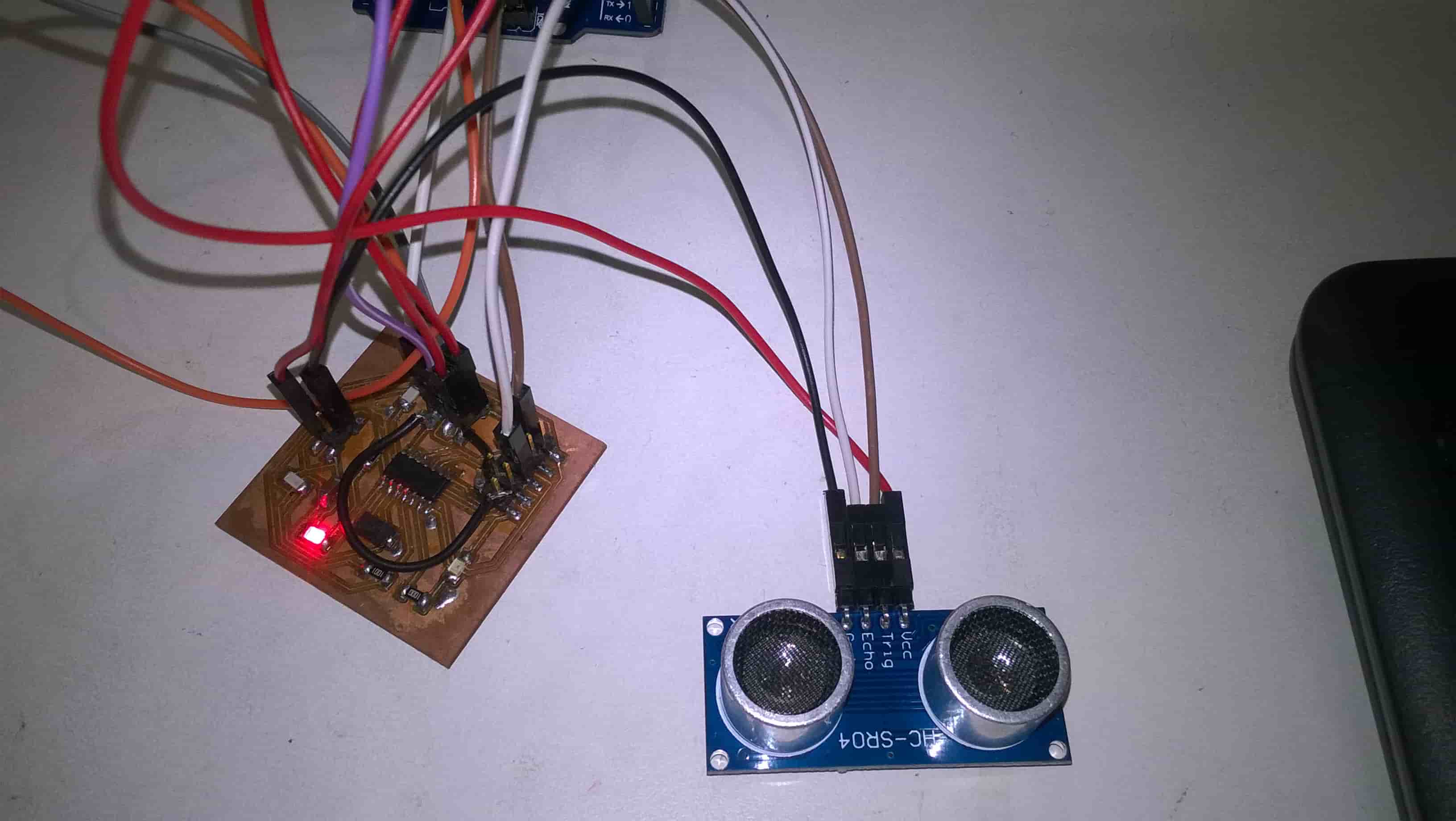
Ultrasonic Sensors are self-contained solid-state devices designed for non-contact sensing of solid and liquid objects. For many applications, such as monitoring the level of water in a tank, ultrasonic technology lets a single device to do a job that would otherwise require multiple sensors. This module includes ultrasonic transmitters, receiver and control circuit. It's 4 pinned device requies 5V DC Supply and a working current of 15mA. It has a maximum range of 4m and minimum range of 2cm. The four pins are 5V Supply, Trigger Pulse Input, Echo Pulse Output, 0V Ground.
IR Proximity Sensor:
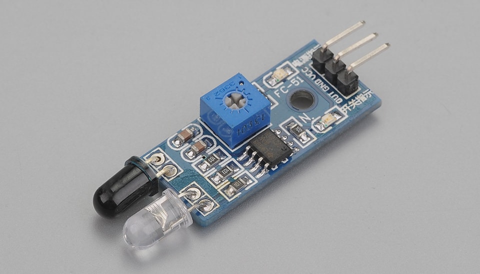
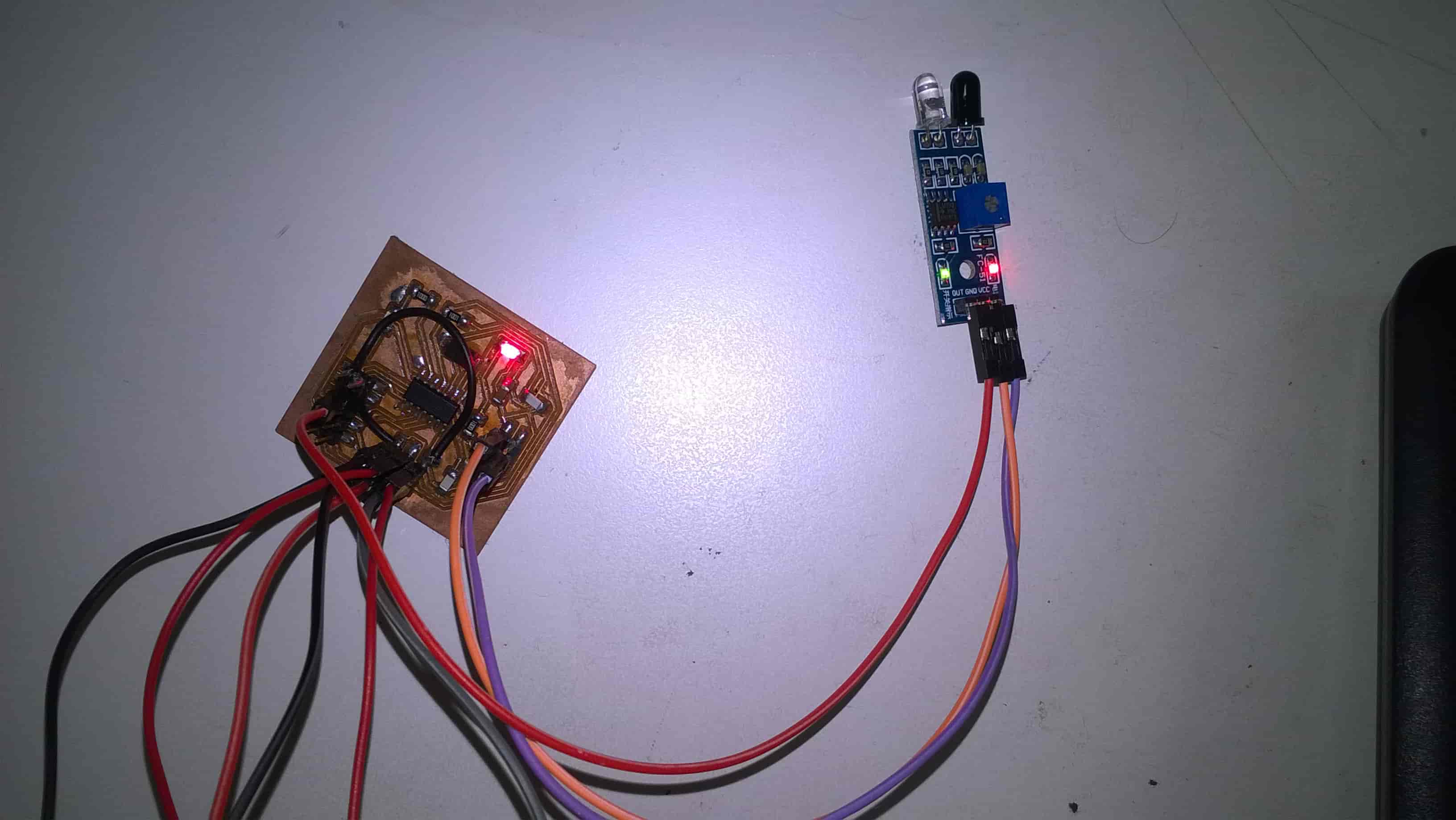
The basic principle behind IR proixmity sensors is that it sends infrared light though IR-LEDs, which is then reflected by any object in front of the sensor. The returning light is received by a detector. The sensor I am using has output varying from 3V to 5V and gives a decent input range from 5mm to 300 mm away. Connection: VCC-VCC; GND-GND; OUT-IO
Switch as Sensor:
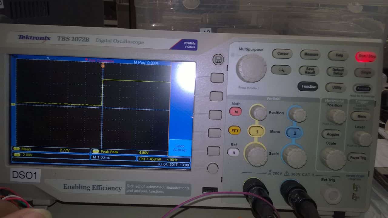
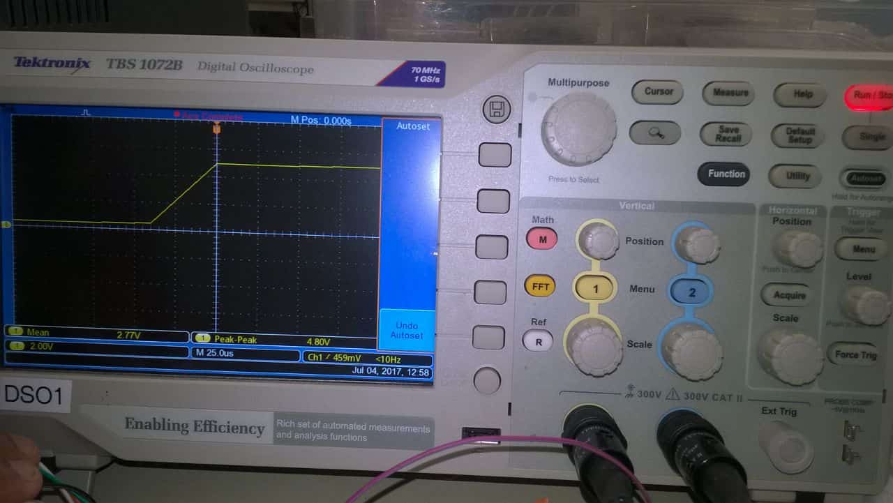
The basic principle behind Switch Sensor is that as the Button on the Board is pressed the LED will blink and the output will be shown on DSO (Digital Storage Oscilloscope) in the form of Sin Waves. The sensor I am using has output of 5V. Connection: VCC-VCC; GND-GND; OUT-IO
Design:
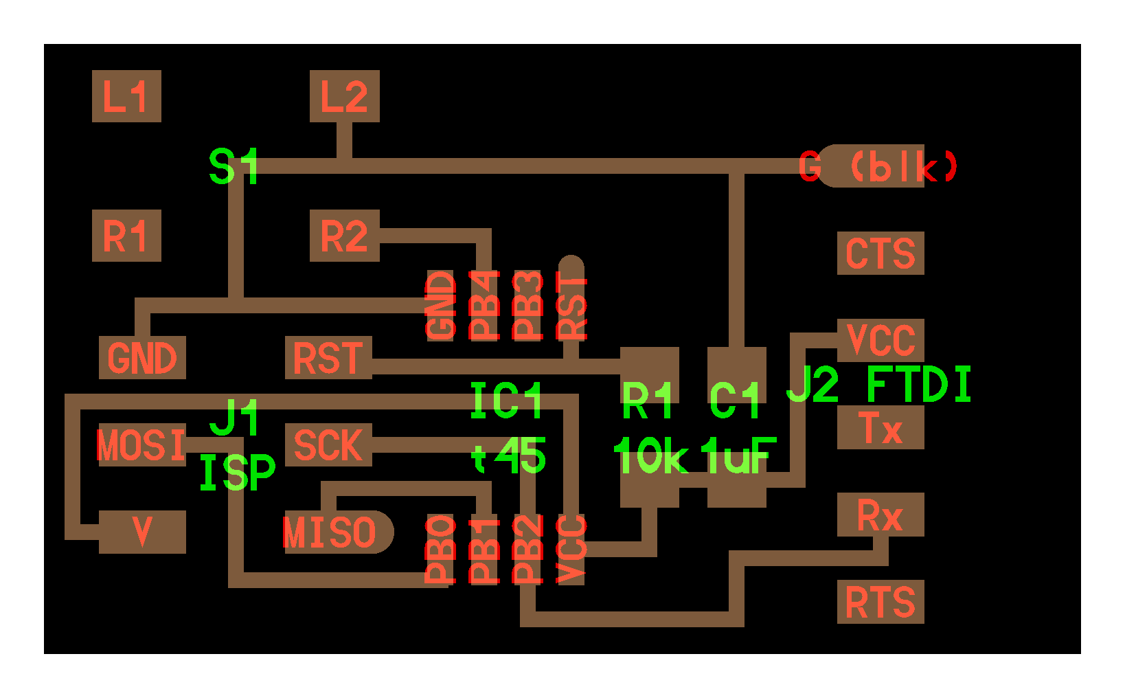
Switch as Sensor:
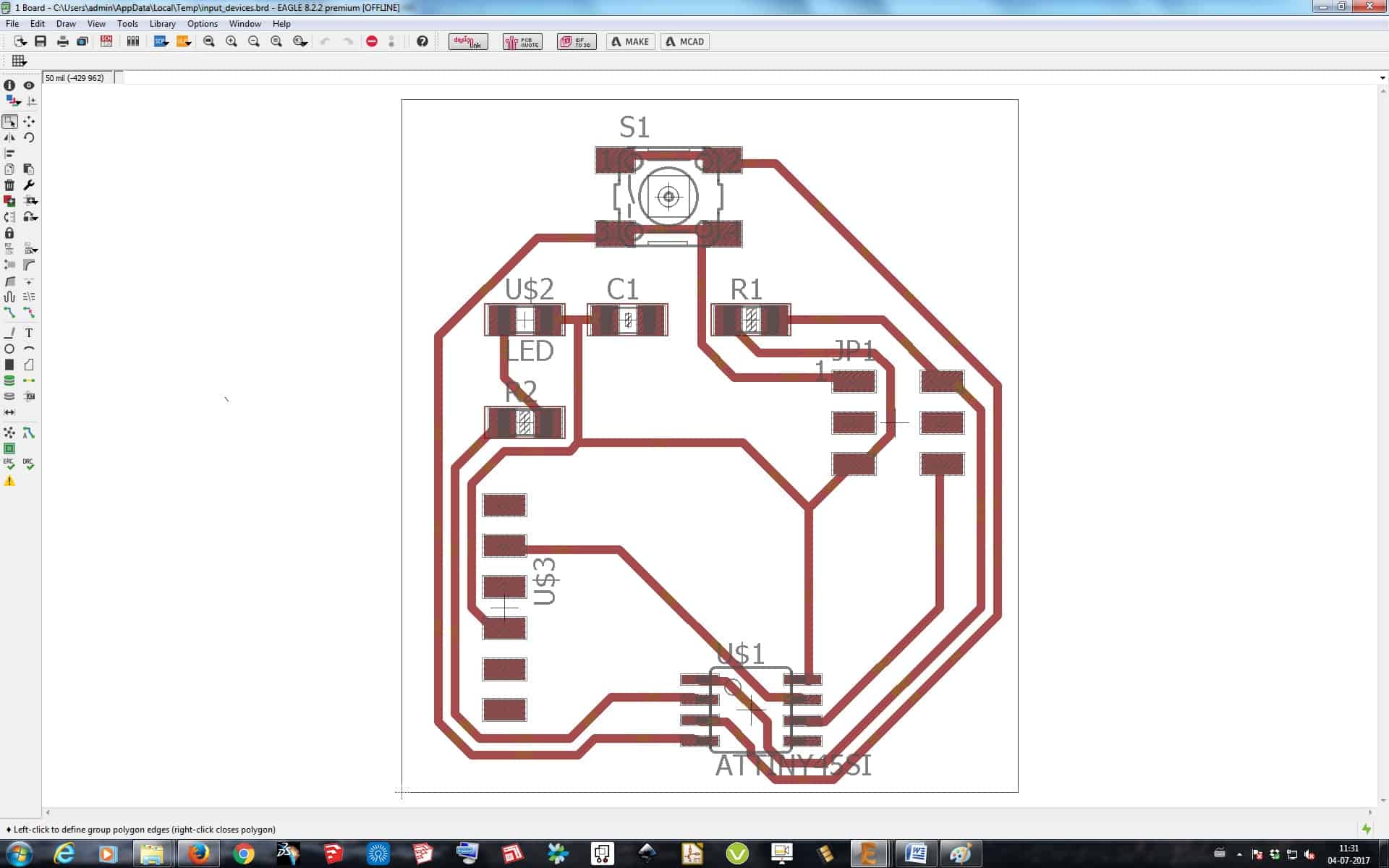
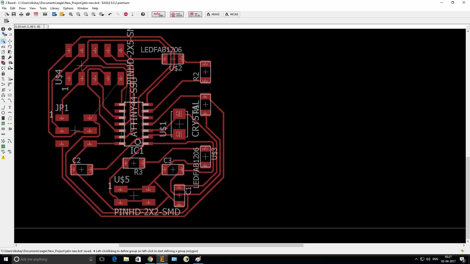
I made a new sensor board taking reference from Neil's Board in the class schedule page under Input Devices assignment. The reference board is shown below:
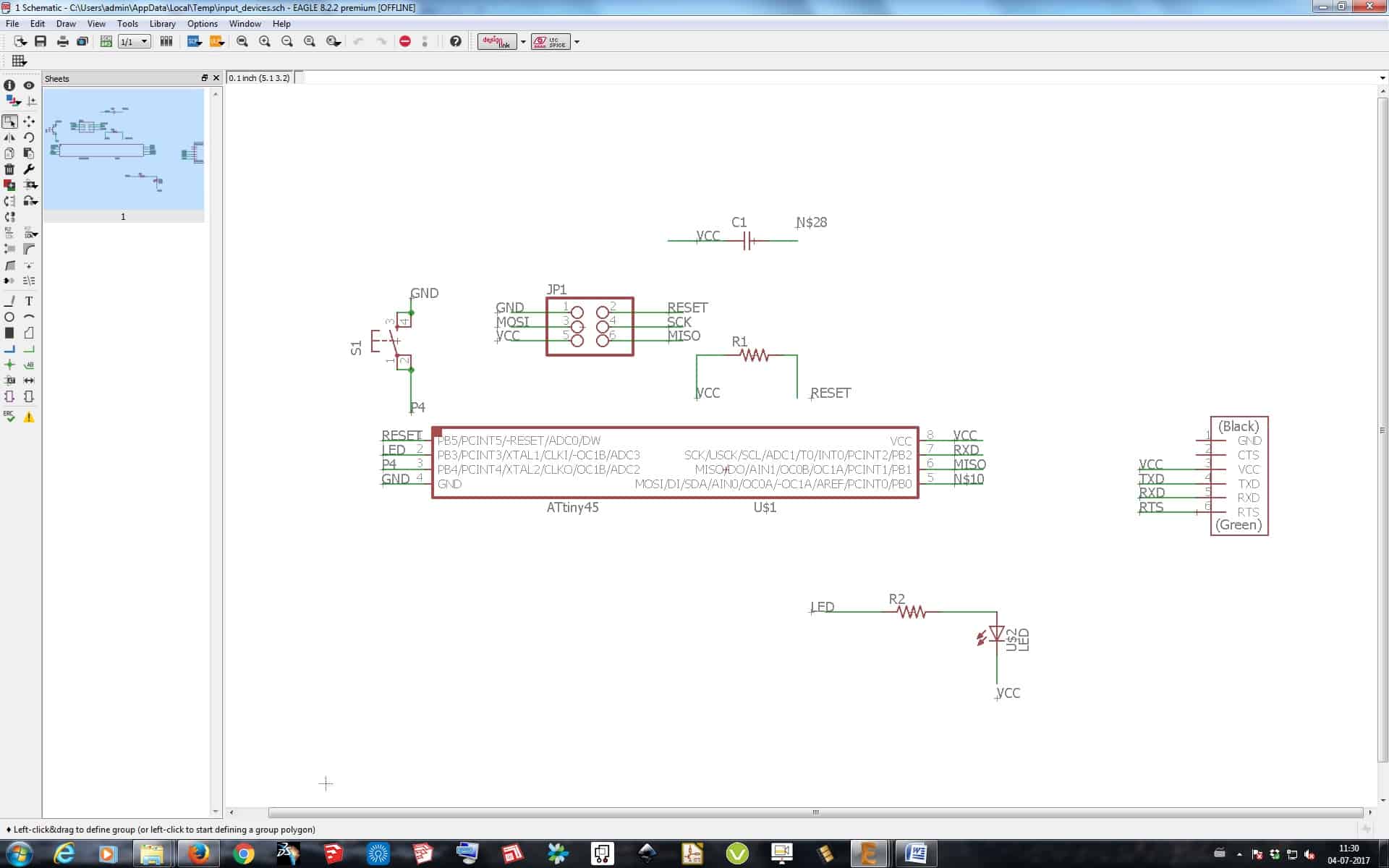
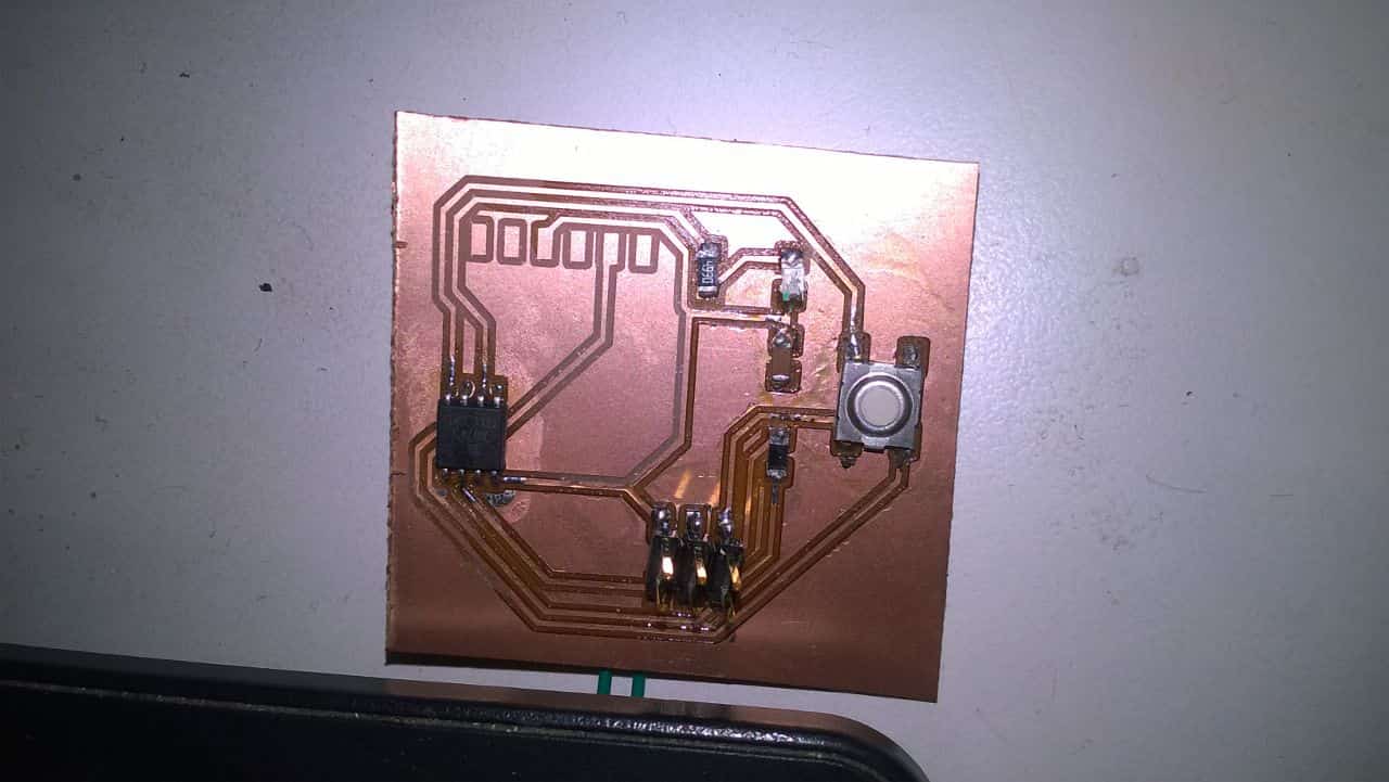
I made the board in Eagle and added a LED in the board so that as I press the button the LED should blink on the board indicating it proper working.
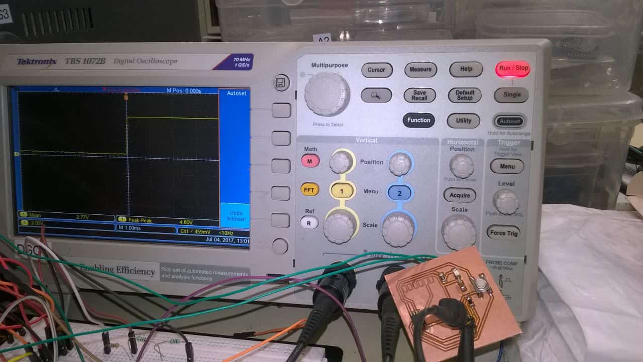
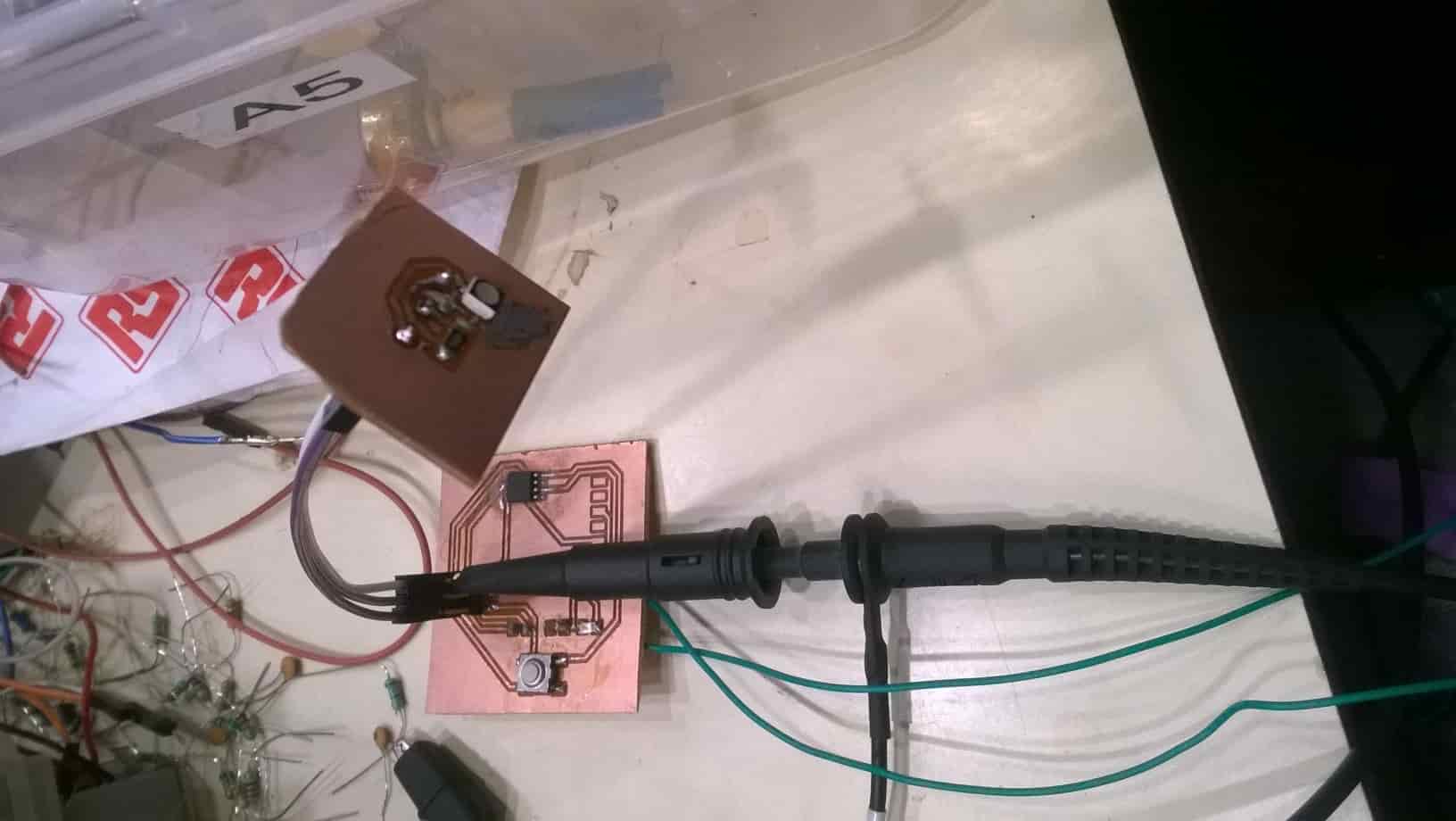
Board Connecting to DSO
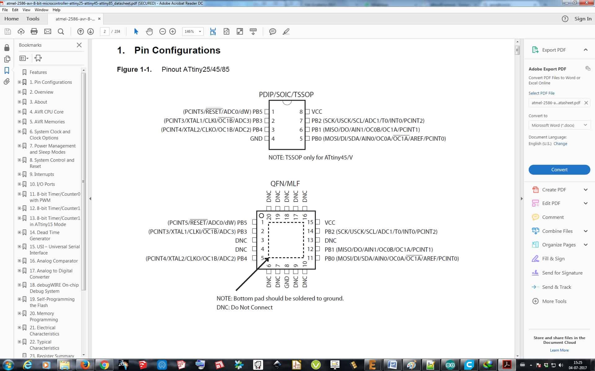
Data Sheet
I used Attiny 45 as a Microcontroller in this Assignment. I had a brief read of Data Sheet for Attiny 45 in this Assignment only I have also attached data sheet for download with files below.
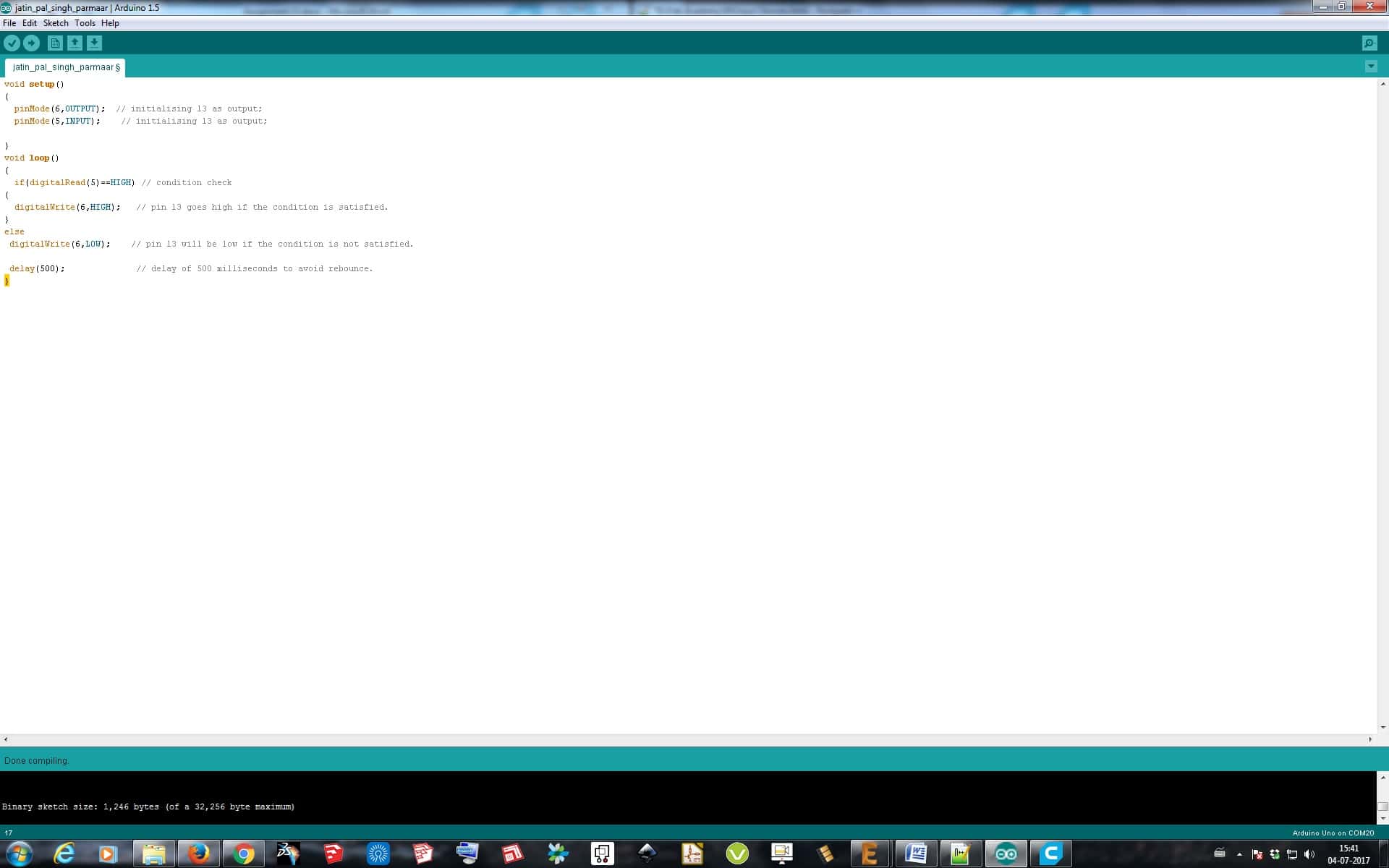
Programming of Switch as Sensor:
For Programming the Microcontroller board I used Arduino IDE to Program. So I did all the previous process in Arduino IDE which I did in Electronics Production Assignment and burned the bootloader. I programmed the board such that as I press the button, LED on the Board will blink and I then attached the MISO and GND pin with the DSO probe. I programmed the board and gave it external power from VCC and GND through Power Supply connecting the wire from down side of the board.
void setup()
{
pinMode(6,OUTPUT); // initialising 6 as output;
pinMode(5,INPUT); // initialising 5 as Input;
}
void loop()
{
if(digitalRead(5)==HIGH) // condition check
{
digitalWrite(6,HIGH); // pin 6 goes high if the condition is satisfied.
}
else
digitalWrite(6,LOW); // pin 6 will be low if the condition is not satisfied.
delay(500); // delay of 500 milliseconds to avoid rebounce.
}
Output on DSO
Video for Switch as Sensor:
LDR Sensor
A photoresistor (or light-dependent resistor, LDR, or photoconductivecell) is a light-controlled variable resistor. The resistance of a photoresistor decreases with increasing incident light intensity; in other words, it exhibits photoconductivity. A photoresistor can be applied in light-sensitive detector circuits, and light- and dark-activated switching circuits.
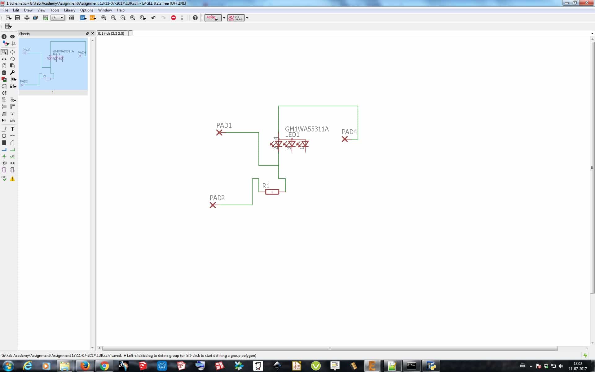
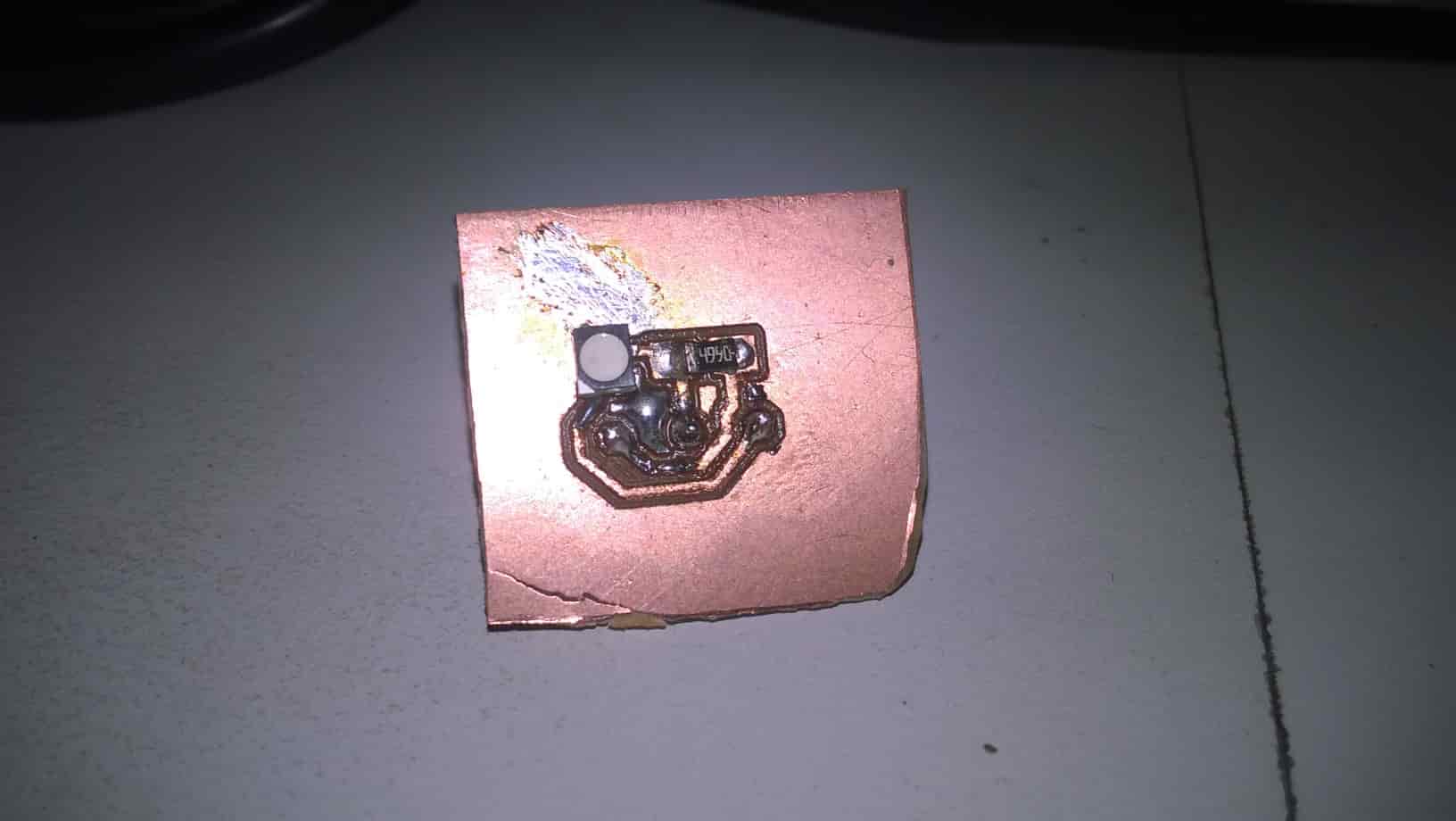
Basically in Simple words what I did here is, I made a simple LDR Board with just LDR in it and 3 PINs coming from it, one for 5V supply, one for Ground, and one Signal Pin, so this board I connected with the Board I made above with a switch sensor, and attached it with DSO, so that as I move my hand in front of the LDR DSO will give signal change on DSO.
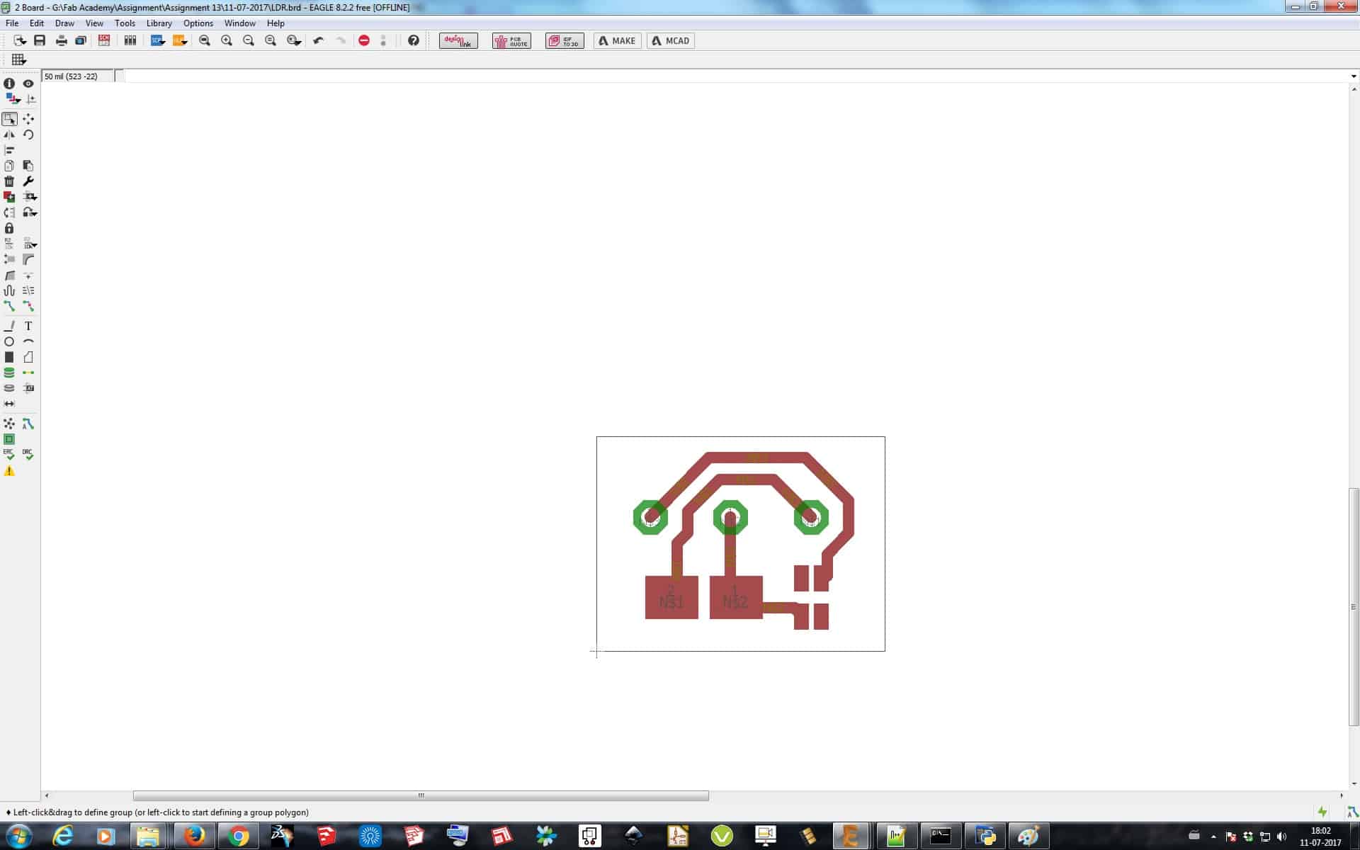
Design of Baord:
Programming for LDR
I connected the LDR board's 5V, GND & Signal Pin to the Switch Sensor Board which I made and gave power to Switch Sensor Baord externally after uploading the program in it using the Arduino IDE software. I used PIN 6 & 7 from the IC for programming the LDR Board. Program can be seen below and all the files are available to download at the end of the assignment.
int sensor_pin = PB2; // defined sensor pin
void setup() {
pinMode(sensor_pin, INPUT);
pinMode(PB1, OUTPUT);// Declared output pin to check values on DSO
}
// the loop routine runs over and over again forever:
void loop() {
// read the input pin:
int sensorValue = digitalRead(sensor_pin);
if(sensorValue==0)
{
digitalWrite(PB0, HIGH);
}
else
{
digitalWrite(PB0, LOW);
}
}
Video for LDR Sensor
IR and Ultrasonic Sensor
Design:
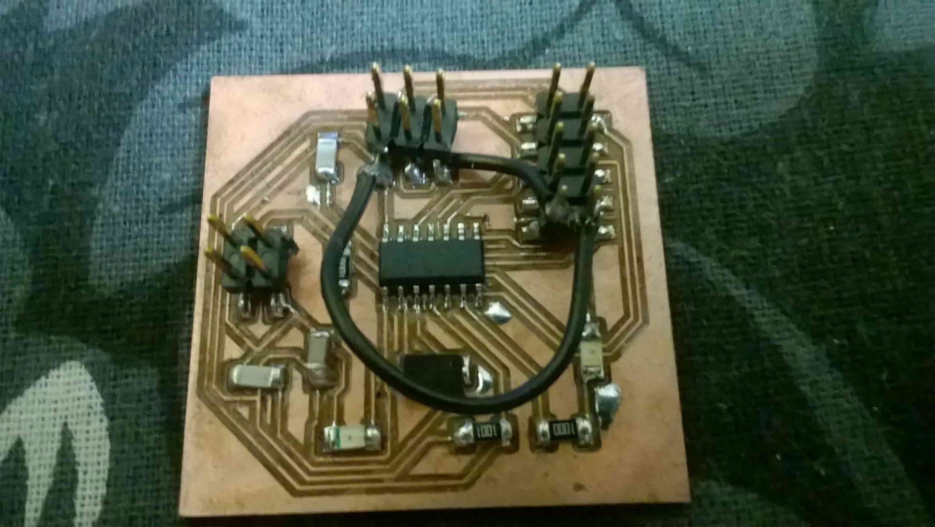
I used IR and Ultrasonic Sensor Module board also for this assignment, in my Output devices assignment as I mentioned in that also, I had designed a board such that it could easily be used in my Input Devices assignment also, so I used the same board which I designed in my Output Devices Assignment, and connected my IR Proximity Sensor Module and Ultrasonic Sensor Module to it and make it work.
Programming of IR Proximity Sensor:
For Programming the Microcontroller board I used Arduino IDE to Program. So I did all the previous process in Arduino IDE which I did in Electronics Production Assignment and burned the bootloader. Now I started programming the board.
int LED = 0; // Use the onboard LED of Microcontroller
int isObstaclePin = 7; // This is our input pin
int isObstacle = HIGH; // HIGH MEANS NO OBSTACLE
void setup() {
pinMode(LED, OUTPUT);
pinMode(isObstaclePin, INPUT);
Serial.begin(9600);
}
void loop() {
isObstacle = digitalRead(isObstaclePin);
if (isObstacle == LOW)
{
Serial.println("OBSTACLE!!, OBSTACLE!!");
digitalWrite(LED, HIGH);
}
else
{
Serial.println("clear");
digitalWrite(LED, LOW);
}
delay(200);
}
Video for IR Sensor
Programming of Ultrasonic Sensor:
// defines pins numbers
const int trigPin = 9;
const int echoPin = 10;
// defines variables
long duration;
int distance;
void setup() {
pinMode(trigPin, OUTPUT); // Sets the trigPin as an Output
pinMode(echoPin, INPUT); // Sets the echoPin as an Input
Serial.begin(9600); // Starts the serial communication
}
void loop() { // Clears the trigPin
digitalWrite(trigPin, LOW);
delayMicroseconds(2); // Sets the trigPin on HIGH state for 10 micro seconds
digitalWrite(trigPin, HIGH);
delayMicroseconds(10);
digitalWrite(trigPin, LOW);
// Reads the echoPin, returns the sound wave travel time in microseconds
duration = pulseIn(echoPin, HIGH); // Calculating the distance
distance= duration*0.034/2; // Prints the distance on the Serial Monitor
Serial.print("Distance: ");
Serial.println(distance);
}